Thursday, December 24, 2015

Introduction to Rapid Prototyping: Robotics - Part 1: Motion Control

Everyone is fascinated with robots and smart gadgets, they are cool and help you get stuff done easier, quicker, with less money and time wasted, how to get there?, how to build a small inexpensive robot to water plants if you forget, or feed your cat while you are at work, in this article of the “Introduction to rapid-prototyping” series I’m going to list and discuss all necessary skills and tools you need to a build a home-made robot, not only that but will cover many basics that you can use to build any control system for any other purpose like home automation & smart homes, intelligent appliances, light controls…etc, so let’s get started.

Closed-Loop Control Model:

First before we start talking about robots let’s go through some basic principles you need to know, basically the robot you want to build is a smart machine, not necessarily a super smart one but it is, so your robot should act like a human in his basic instincts which is: sense, understand, decide then act based on inputs from the surrounding environment to him (the robot), this is formalized in the “Closed-loop Model” like the one shown in the figure below.
Basically the closed-loop model defines the need for a closed path between sensings element in the system (e.g. human senses like touch, see smell…etc), its analytical and decision unit (e.g. the brain) and its actuation (e.g. muscles) for act smartly to the surrounding, so, basically in robotics we try to imitate this basic human instinct using the closed-loop model.

Figure 1: Closed-Loop Control Model

Modes of Control:

Once the closed-loop based control system we are aiming to build is up and running there will be a need to control it, either having direct control on it via an operator (human operator) using a “Drive-by-Wire” mechanism (e.g. using a remote control or a joystick to do so), or program it to be completely independent of its operator and operate autonomously, or the third option is to program the system with the ability to collaborate and communicate with other operators and/or peers, which in this case the smart machine (i.e. the robot) can collaborate and communicate his sensor readings and/or future or past actions to another smart machine, so, let’s summarize the three modes of control for a robot or an intelligent control system:
  •  Tele-operated mode.
  • Autonomous mode.
  • Peer-to-Peer mode.

 Electric Actuation:
 We are done from the foundation required to understand how robot works, now let’s move to the details of each block of the closed-loop model and understand how to use and deploy within your robot design, and let’s start with the “muscles” of the robot or the actuators, mainly robots use electromechanical actuators (i.e. electric motors) since they have smaller physical profile, faster response and easiness to control via electronic modules more than gas or mechanical engines, the four types of electric motors used in robotic applications are:
  • DC motors:

Our first type of electromechanical motors, they convert direct current (DC) to a continuous rotary motion, direction of is based on the voltage polarity on the motor terminals.
 
Figure 2: DC motor motion with respect to the polarity of the voltage supply applied to it.
Figure 3: Simple DC motor driver using on/off switches
  • Stepper motors:

Unlike DC motors, this type of motors moves in steps i.e. motion is discrete, the angle per step is a motor-design dependent e.g. some motors move 3.6 degrees per step (100 steps per revolution), others are 1.8 degrees per step (200 steps per revolution), which mean it doesn’t require a feedback to know where the motor shaft has stopped, by the number of pulses you supply via the driver it will move a certain number of steps, there are two types of steppers:
o   Unipolar stepper motors.
o   Bipolar stepper motors.
Both of them function in the same way, moving steps, but their internal designs are different and same for their driving circuits, later in this article we will discuss the driver circuits for both types of stepper motors.
  • Servo motors:

Servo motor is a modified version of the DC motor with an embedded feedback-control unit to know the shaft position at each moment plus gearing to increase motor’s torque (increase motor’s force, i.e. ability to lift/drag more weight or put more pressure). This type moves in “angles”, not pre-defined steps, so it can rotate to any angle. To drive it you must supply the motor with a control signal to determine the angle the shaft will stop at using Pulse Width Modulation (PWM) technique (to be discussed in detail later).

  •   Brushless DC motors (BLDC):

Though this type of motors is called “Brushless DC” but its supply isn’t really DC, the basic BLDC design consists of three coils from inside; to drive it each coil is supplied with a 90 degrees phase-shifted square wave signal (or sine wave), this type is very commonly used with drones and helicopters because of its high speed compared to the other three types.

Motor Drivers and Controls:
To drive an electric motor we need an electronic circuit that can:
  • Give the motor the appropriate signal required (like continuous supply in case of DC motors, pulse sequence in case of steppers, PWM in case of servos and 90-dgrees phase shifted pulses in case of BLDCs).
  • Power driver, it is the part of control circuit that will switch on and off based on the control signal, where it has to be able to stand the amount of voltage and current supply the motor requires.


Power Drivers:
In figure 3 we showed how to drive a DC motor using simple on/off switches and where these switches can be placed: either between the supply and the motor or between the motor and the ground/common of the supply, the first one is called a “source driver” or the second is called “sink driver”, and since the robot we aim to build is fully electronic so we will need to replace the mechanical switches in figure 3 with electronic ones, here where relays and transistors role come, so the driver will become like:

Figure 4: DC motor source driver using NPN transistor (on the left), and using a relay (on the right).

Transistors, either BJTs or MOSFETs, are a very common element in building power drivers for electric motors, relays are useful but they have two issue:
  • Very high switching time compared to transistors.
  • Relay’s coil can’t be driven directly from the electronic control unit because it relatively consumes a lot of power and requires its own power driver circuit.
So relays aren’t the best element to use for motor power drivers but still used in some applications.
For high power motors regular transistors aren’t able to stand the current/voltage supply required to drive the motor, so there is a need for power transistors since they can drive much higher current than regular ones.
An improved version of the transistor-type power driver is the “Push-Pull driver” because it can work as source-sink driver in the same time, no need to change the circuit design with any changes in the motor-supply connection like in the following figure:
  
Figure 5: Push-pull driver for both sink (bottom) and source (up) cases

In figure 5 on the left the push-pull driver works as a sink driver, when there is no input signal the P-MOSFET transistor is on and the N-MOSFET one is off, providing a way between the motor and the ground, while the push-pull driver on the right is a source driver, when the input signal is supplied to the gates of the transistors the N-MOSFET is on while the P-MOSFET is off, connecting the supply to the motor.
Example of popular power drivers for electric motor:
  • TIP41: NPN power transistor that can supply up to 5A.
  • TIP42: the PNP version of TIP41 transistor.
  • TIP122: a power darlington pair that can supply 5A.
  • ULN2003A, ULN2803: both chips contains an array of 8 sink driver that are capable of sinking 500 mA per each driver.
  • L293: four push-pull drivers packaged in one chip that is capable of source/sink of 1A.

Driving DC Motors:

Earlier we said that changing the voltage polarity of the supply to a DC motor will change its direction of motion, this is not feasible manually, also can’t be done with only one switch/switching element in the circuit, so engineers came up with this design to change the supply polarity on a DC motor:


Figure 6: polarity switching driver for DC motors (far left), theory of operation (middle and far right).

This circuit uses two switches at a time to change the voltage supply polarity across the terminals of a DC motor, so if switches 1 and 3 are on together circuit is closed and the motor will rotate in one direction, if we do the same with switches 2 and 4 the motor will start rotating in the opposite direction.
In the previous circuit we explained it using switches, but in reality the robot’s brain can’t press on mechanical switches to turn them on/off, the switches must be electronic using transistors, so the circuit can be redesigned using 4 NPN BJT transistors to become like:
Figure 7: H-bridge circuit using 4 NPN BJT transistors
How does it work?
When input 1 is activated with a voltage signal (while input 2 isn’t) transistors Q1 and 45 will turn on to let the current go to the motor through Q1 then ground through Q4, when input 2 activated (and input 1 must be turned off) transistors Q2 and Q3 will turn on letting the motor to get its supply via Q2 and connect to ground via Q3, reversing the direction of motion.
Because this circuit consist of two arms connected to the DC motor similar to the letter “H” so it is called “H-bridge circuit”.

Driving Steppers:

Earlier we mentioned that there are two types of stepper motors with different internal designs but nothing is different in how they operate, both move steps either forward or backward, the first type of steppers is “Unipolar stepper motor” and its internal design has four coil windings as shown in figure 8 (left), while the bipolar has two coil windings only, figure 8 (right).
                                    
Figure 8: Unipolar stepper motor internal design (left) and Bipolar stepper motor internal design (right)


Figure 9: Winding types for unipolar stepper motor
         
    
Figure 10: Unipolar stepper motor drivers for Japan servo winding (up) and copal winding (bottom).

For a unipolar stepper, there are different modes to activate the windings depending on the torque or speed required, mainly there are three modes to drive a stepper:
  • Wave drive: to activate one winding at a time while the rest are off, then activate the next while the rest are off then the next then the last winding, activation sequence looks like that:

Coil A
Coil B
Coil C
Coil D
Activated
Off
Off
Off
Off
Activated
Off
Off
Off
Off
Activated
Off
Off
Off
Off
Activated

Activated means the winding is supplied with a pulse, though the drive is very smooth but this mode doesn’t offer much of a torque.
  • Full drive: In this mode two coil windings are activated at a time, less smooth in motion but gives a higher torque than wave drive, windings activation sequence looks like that:

Coil A
Coil B
Coil C
Coil D
Activated
Activated
Off
Off
Off
Activated
Activated
Off
Off
Off
Activated
Activated
Activated
Off
Off
Activated
  •        Half drive: in this mode the sequence is activating two windings then one then two windings then one and so on, it gives double the resolution of the motor, i.e. if your motor step size is 3.6 degrees this mode makes move on steps of 1.8 degree, the drive sequence as follows:

Coil A
Coil B
Coil C
Coil D
Activated
Off
Off
Off
Activated
Activated
Off
Off
Off
Activated
Off
Off
Off
Activated
Activated
Off
Off
Off
Activated
Off
Off
Off
Activated
Activated
Off
Off
Off
Activated
Activated
Off
Off
Activated

Connections: in the unipolar stepper, the common wires are connected to the voltage supply of the motor, while the coils terminals are connected to ground via switching element (power transistors or push-pull drivers), where the activation sequence is fed to the switching elements based on the driving mode as explained above.

For bipolar stepper, its different because of the coil winding structure, it has only two coils, the sequence to drive it is to activate the first coil winding then the second one then the first with a reverse voltage supply then the second with a reverse voltage supply, a bipolar stepper requires two H-bridge circuits to drive it.
Figure 11: Bipolar stepper motor driver using 2 H-bridge circuits

Control sequence for the control circuit shown in figure 11:
Input 1
Input 2
Input 3
Input 4
Activated
0
0
0
0
Activated
0
0
0
0
Activated
0
0
0
0
Activated

Voltage across stepper motor winding will look like the following:
Lead A1
Lead B1
Lead A2
Lead B2
Positive supply
Off
ground
Off
Off
Positive supply
Off
ground
ground
Off
Positive supply
Off
Off
ground
Off
Positive supply

Speed of stepper motors depend on the frequency of the sequence, however this sequence isn’t infinite, sequence speed usually is very low between 0.1 and 20±5 Hz.
You can create the driving sequence using a microcontroller or a programmable device or use a stepper motor driver IC, then combine your design with the required switching element for either motors, the following ICs are useful for stepper motor:
  •  L297: stepper motor driver.
  •  L298: two H-bridge circuits in one IC, can supply output current of 2A to each motor.
  • LM18245: H-bridge IC, can supply output current of 3A to a motor.
  • LM18200: H-bridge IC, can supply output current of 3A to a motor.
  • DRV8848: two H-bridge circuits in one IC, can supply output current of 2A to each motor.  

Pulse Width Modulation:

Pulse Width Modulation, or PWM, is a technique to vary signal amplitude level by on/off fast switching of this desired signal, it can be used to change the speed of an electric motor by varying the amplitude of the input voltage supply. Also used in position control for servo motors.
First, let’s start with an example, if we have a voltage supply that’s turned on for 10 mili-second then off for another 10 mili-second, that means the signal is 50% of the time on and 50% of it off, if switching is happening at a relatively high frequency for the actuator (electric motor in our case) then it won’t sense the on/off switching but the average voltage, which in this case it is 50% of the voltage supply. The time where the voltage signal is high (on), is called “duty cycle”, and the whole period from the start of a duty cycle to the start of the next one is called the “period”, so simply the higher the duty cycle the higher the average voltage supply sensed by the actuator.

Let’s have a look on this example:
If I have a voltage supply of 10v maximum supplied to a DC motor through a PWM controller, if the duty cycle (duration of time the voltage supply is turned on) is 3 mili-second and the total period is 10 mili-second, what is the average voltage supply getting to the actuator?
First let’s find the duty cycle in percentage = (3 mili-sec/10 mili-sec) x 100% = 30%
The average voltage supply to the DC motor = 30% x 10v = 3v, so the DC motor is actually supplied with 3v only even though the supply voltage is 10v, figure 9 shows more examples of PWM.

Figure 12: varying average voltage using PWM

Position control using PWM:
Servo motors use PWM to control the shaft position, the input control signal of a servo motor has a period of 20 mili-second, depending on the duty cycle the internal control circuit of the motor moves the shaft to a specific position, figure 10 shows the duty cycle required to move a servo motor to positions 0°, 90° and 180°.
Figure 13: servo motor PWM control signal

Electrical braking and protection:
There are two ways to stop an electric motor:
-        Mechanically using brakes.
-        Electrically by shorting the motor coil terminals together, so the internal energy stored in the coil is dissipated, this method is easier to implement and decreases time to bring the motor to a complete stop. It can be implemented just by placing a relay across the motor coil terminals and activate it when we need to stop the motor, figure 11 shows simple electrical brakes.

Figure 14: electrical braking system

Another critical issue for coil-based electric actuators like motors, relays and solenoids is the “inductive kickback”, the internal coil of the actuator stores energy as long as it is supplied and operating, but once it is turned off the coil tries to dissipate all this stored energy in a form of a negative voltage spike that can be high enough to damage any sensitive electronic components like controllers, sensors, integrated circuits attached to the actuator control system, to protect the electronics from damage we connect a diode between the low-end of the actuator (the terminal connected to ground) and the power supply similar to the one in figure 12, this diode configuration is called “flyback diode”.
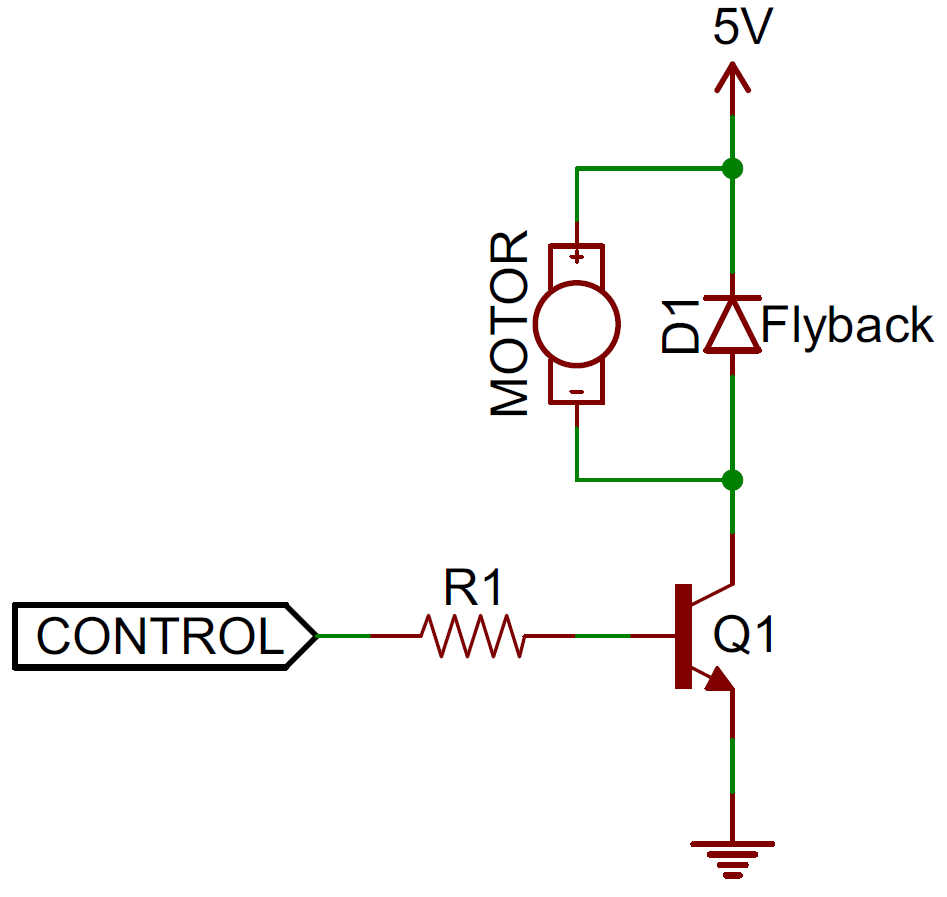
Figure 15: Flyback diode
Position sensing:
There two popular types of sensors used to sense the motor shaft position:
  •  Hall Effect sensors: they sense the magnetic field from the motor coil or from a magnetic or ferromagnetic material mounted on the motor shaft.
  • Optical encoders: basically they are optical sensors; internally they have a source of light, light sensor and a specially designed desk that blocks the light from reaching the sensor when it moves. The desk’s shaft is mounted to the motor’s shaft to sense the motor angular motion and output either an analog or digital code equivalent to the motor position. 
In part two of this article we will expand in explaining basic sensors and some advanced sensors for feedback, decision-making & control using microcontrollers, remote control via different wireless links and finally some mechanical design ideas for robotics, see you soon :)

Karim El-Rayes,
Vancouver, Canada
December 23, 2015

Wednesday, March 11, 2015

Introduction to Rapid Prototyping: Wearable Devices

“Wearables”, the word that defines the next revolution in consumer electronics, gadgets are moving from being portable or mobile to being simply…wearable, either embedded inside your shirt fabric or around your wrist, in your shoes or in the necklace you are wearing, and even inside your sunglasses, anything you wear or touch your body can be employed as a mount for such gadgets to either measure your biological vital signals like body temperature, pulse rate, blood pressure, motion & physical activity, muscles, heart & brain activity, and/or provide you with real-time assistance like geo-navigation, healthcare monitoring, personal assistance (appointments calendar, to-do list…etc.).
In this article we will discuss main guidelines of designing and prototyping for wearable devices, the basic rules for prototyping doesn't differ much than the ones discussed previously in the first two articles in the series “Introduction to Rapid Prototyping, adding to them the following guidelines to complete the full picture:
  • It has to be light weight (both the gadget and power source).
  • With very small physical profile.
  • Ultra-low power consumption.
  • Easy user interface.
  • Flexible, so it can be shaped on human body.
  • Easy to install and setup.
  • Material made of has to be skin-friendly and never cause any biohazard (e.g. skin irritation, allergies…etc).
  • The gadget has to be electrically safe (no electric shocks, short circuits, dissipated heat).
The three stages of a wearable device: 1. Sensing, 2. Signal processing, digitization, data processing & storage,  3. Data transmission to a remote host for further analysis and visualization.
Sensors:
Sensors are electronic devices that convert physical quantities like temperature, light, motion…etc. to electric signals so to be easily interfaced to a computer, since computers don’t understand anything except electric signals (this simple definition of sensors targets non-technical readers).
Let’s make a list of the physical quantities a wearable gadget would measure and sensors that can be used in each case:
Physical quantity
Example
Sensor
Suggested mounting
 Motion (for humans or objects)
Walking, running, physical exercising.
Accelerometer can measure object acceleration.
Gyroscope can measure tilting/angle of inclination.
Wristband, embedded in shoes or fabric.
Heart rate
Heart pulse rate per minute
Pulse rate sensor
Wristband, ear clip.
Fatigue and exhaustion
Heart activity
Electrocardiogram (ECG)
Embedded in fabric.
Body temperature
Skin surface temperature, ambient temperature
Thermistor & thermocouple sensor.
Wristband, embedded in fabric
Shock
Physical impact
Piezoelectric shock sensor
Embedded in shoes/footwear.
Force
Weight, muscle strength/force
Strain gauge
Embedded in shoes/footwear.
Touch
Finger tips touch
Capacitive pads
Embedded in fabric.
Light
Ambient light, reflected light from a certain source
Photo-diode.
Wristband, finger clip.
Surface bio-signals
Muscles and limbs activity
Electromyogram (EMG)
Embedded in fabric/cloth.
Mental stress/activity
Brain activity like concentration, stress, emotion
Electroencephalogram (EEG)
Embedded in eyeglasses or headwear.

Example of off-the-shelf sensors and modules:
·       MXR7900: 2-Axis accelerometer from MEMS IC can measure up to ±0.5g acceleration in X- and Y-Axis.
·       LPY503AL: 2-Axis gyroscope from ST Microelectronics can measure up to ±30° degrees in yow- and pitch-directions.
·       TMP36: Ambient temperature sensor IC from Analog Devices.
·       OPT101: Ambient light sensor IC from Texas Instruments.
Power storage
The wearable device requires a power source to keep it running for enough time to do the required measurement or assistance to the user; however the known constraints of physical profile and weight of the wearable device must be taken into consideration when choosing the power source.
So far batteries are the best option for wearables in terms of physical profile and portability, however they aren’t sustainable and require replacement or recharging on regular basis, there are three different kinds of batteries available in the market for wearables:
  • Lithium Ion (Li-ion) batteries: the most commonly used type of batteries used in electronics, with the advances in technology it comes in different shapes and forms (flexible and solid).
  •  Solid-state batteries: made of semiconductor materials, usually meet the size require but have a very low capacity compared to Li-ion ones.
  • Super-capacitors: a high capacity electrochemical capacitors, their size and leakage problem are the main obstacles to use them in wearables. 
Energy harvesting
Another way of providing electric power to wearables is energy harvesting (AKA. energy scavenging), it is the process of converting waste energy from the surrounding environment found in the forms of heat, motion or light to usable electric power, this field is fairly new in comparison to batteries and research didn’t achieve to a revolutionary design that can replace batteries or any other form of energy storage till the date of the article. There are three types of energy harvesting based on the waste energy they harvest:
  • Thermal energy harvesting: harvesting waste heat from the surrounding environment or  from human body, Thermoelectric Generator (TEG) is used for this purpose.
  • Vibrations energy harvesting (VEH) is the process of harvesting waste kinetic energy resulted from motion and vibrations into electricity by the means of electromagnetic, electrostatic or piezoelectric transduction.
  • Solar energy: as most of readers have read or saw it before working, Photovoltaic (PV) cells are used to convert sun light to electricity and by far it is the most successful form of energy harvesting, solid glass solar panels aren’t easy to use with wearables but flexible solar panels are more convenient and design-friendly. 
Interface & Communication:
Microcontroller Unit (MCU):
The microcontroller is the processing unit of the wearable device responsible of reading the signals from sensors, process them to become useful data, display it to the user and finally communicate it if required with any external device via wired (USB as an example) or wireless means (Bluetooth, Zigbee…etc.). The microcontroller unit has to meet the power requirement of low power consumption since the whole gadget is running on a limited power supply like a battery, the following microcontroller families are good candidates for wearable designs in the sense of low-power consumption and low cost:
  • Texas Instruments MSP430, 16-bits RISC CPU.
  • Microchip PIC18 and PIC12, 8-bits RISC CPU.
  • ST Microelectronics STM8, 8-bits RISC CPU.
  • Atmel ATmega, 8-bits RISC CPU.
Data display and communication:
Another important feature a wearable gadget must have is data display, either by sending it to an external device or on the gadget itself using a small LCD display or LED indicators, and because of the of limitations in power supply and physical profile design most wearable designers prefer to send data to an external device for display. There are two ways to communicate data to external world:
  • Data is stored on an on-board memory then the user can retrieve it by connecting the gadget to a computer or a smartphone wired or wirelessly using USB, Bluetooth, Wi-Fi or Near Field Communication (NFC).
  • Data is communicated in real-time to a nearby device via short range wireless technologies like Bluetooth, Wi-Fi, ZigBee or similar protocols.
And here are some wireless enabled boards and modules that can be used for wearables either stand-alone or combined with a microcontroller unit:
Wireless communication between the wearable and display device is the preferred option for designers because it meets the portability and simplicity requirements easily, however this comes on the expense of power consumption since wireless communication modules are relatively power hungry when compared to the rest of the wearable components (MCU and sensors), however designers were able to overcome this problem by either lowering the data rate (speed), range and non-continuous transmission, low power technologies like Bluetooth Low Energy (BLE) and ZigBee use these techniques to lower power consumption and extend battery life.

Other design ideas
  • As discussed previously wearables have to be small and light, also “flexible” if possible to take the shape of the human body/part it is worn on, and here comes the benefit of “flexible printed circuit board” (or Flex PCB), it is made of special polymers to be physically flexible and bend easily without any impact on the electric connections or components mounted on its sides.
  • Conductive threads/plates: can be used to detect electric connectivity from an outside source or help transmitting a specific signal through clothes fabric.
  • 3D printing: to accelerate prototyping of wearable gadgets 3D printing is a good option and much lower in cost in comparison of similar alternatives like mold injection and casting.
Flexible PCB
(Source: http://edablog.com/2009/03/10/utcp-wearable-electronics/)
Components manufacturers
This is a list of the most known manufacturers of sensors and semiconductors that can be used in wearable designs:
  • Inertial sensors (accelerometers & gyroscopes): MEMS IC, STMicroelectronics, Analog Devices.
  • Temperatures sensors: Maxim Integrates, Texas Instruments, STMicroelectronics, Analog Devices, Microchip Technologies.
  • Light sensing: Texas Instruments.
  • Analog Front End (AFE), Analog to Digital Converter (ADC), Sensor interface chips: Texas Instruments, Linear Technologies, Maxim Integrates, Analog Devices, Microchip Technologies.
  • Energy harvesting solutions: Linear Technologies, Texas Instruments, Cymbet.
  • Low-power microcontrollers: STMicroelectronics, Texas Instruments, Microchip Technologies.
  • Flexible solar cells: http://www.flexsolarcells.com/PowerFilm-Solar-OEM-Components.php
For board design the following software tools are quite helpful for PCB layout, schematic capture and 3D design & modelling:
  • PCB layout and schematic capture tools: DipTrace, KiCad, Altium, PCB Artist, OrCad, Mentor Graphics Pads.
  • 3D design & modelling: SolidWorks, AutoCAD Inventor.
And since you have reached this point in the article then possibly you are thinking of building your own board, these companies offer PCB manufacturing services at low cost for prototyping purposes:
Last but not least, this article is meant to be an introductory material for hobbyists and developers interested in learning rapid prototyping for wearable gadgets but it doesn’t cover everything; this article is meant to be your first step, meant to make you more hungry and curious to know more about wearables, so good luck.

--
Karim El-Rayes
March 11, 2015
Vancouver, Canada

Wednesday, November 12, 2014

Introduction to Rapid Prototyping: Internet of Things

Internet of Things, or IoT for short, is one of the new big trends in technology, in brief, it is about making everything and anything connected to the cyberspace of the internet, so you can access your home via your smartphone, or make your car talk to you or to other cars, from the smallest temperature sensor on top of your house to the biggest data centers and servers everywhere are going to be connected, though the matter of data security is still in debate but undoubtedly IoT will help to improve many services.

In this article, we will continue the discussion about different platforms for low-cost rapid prototyping, but we will be more specific and target only platforms suitable for IoT applications, compare them from price and technical perspectives. Mainly an IoT platform needs two features:
-        Internet connectivity, the platform must be equipped with some sort of a connectivity interface to the internet via a wired Ethernet, Wi-Fi, Bluetooth or at least with a USB that is connected to PC or a modem to connect it to the internet or any other sort of networks.
-         Web service: an IoT platform in most cases is required to have an onboard web server, not necessarily an advanced one; in many cases just a light weight web server is more than enough to communicate the data to other peers/terminals.

First let’s start with most common low-cost development kits that support network/internet connectivity via Ethernet and Wi-Fi, though they are quite handy for controls applications, compact form factor applications, home appliances and others but requires a lot of work on the low-level programming side, hardware wiring and packaging:  

-        Arduino YÚN: 66.36$
CPU: Atmega32U4 8-bit RISC.
Connectivity interfaces: wired Ethernet, Wi-Fi and USB
Development environment/IDE: Arduino IDE (C -like programming language).
Website:

-        Arduino Blend: 32$
CPU: Atmega32U4 8-bit RISC.
Connectivity interfaces: Bluetooth.
Development environment/IDE: Arduino IDE (C -like programing language).

-        Tiva C Connected LaunchPad: 20$
CPU: 32-bit ARM Cortex-M4/120 MHz
Connectivity interfaces: wired Ethernet, USB (host or device).
Development environment/IDE: TI Code Composer Studio (C/C++), Energia IDE (the Arduino IDE equivalent for TI Launchpad kits, C –like programming language).

-        SimpleLink Wi-Fi CC3200 LaunchPad: 30$
CPU: 32-bit ARM Cortex-M4.
Connectivity interfaces: Wi-Fi
Development environment/IDE: TI Code Composer Studio (C/C++), Energia IDE (the Arduino IDE
equivalent for TI Launchpad kits, C –like programming language).

-        Intel Edison: 50$
CPU: 32-bit Intel Quark/100 MHz.
Connectivity interfaces: Wi-Fi, Bluetooth.
Development environment/IDE: Edison Arduino IDE.
Note: Requires Arduino expansion kit for development and prototyping purposes.

-        Microchip Comm Demo Board: ~50$
CPU: Microchip 32-bit MIPS
Connectivity interfaces: Wi-Fi.
Development environment/IDE: MPLAB IDE and C32 compiler.
Website:

-        PIC32 Ethernet Starter Kit-I and -II: 75$ and 89$
CPU: Microchip 32-bit MIPS/80 MHz.
Connectivity interfaces: wired Ethernet, USB (host & device).
Development environment/IDE: MPLAB IDE and C32 compiler
Website:

Particle Core (formerly Spark Core): 39$
     CPU: ARM Cortex-M3/72 MHz.
     Connectivity interfaces: Wi-Fi.
     Development environment: Web-based IDE using REST API.
     Website: https://www.particle.io/

NodeMCU: ~7-13$
    CPU: 32-bit Xtensa LX3 Architecture (A.K.A. ESP8266).
    Connectivity interfaces: Wi-Fi.
    Development environment: Lua, ESPlorer, Arduino IDE.
    Website: www.nodemcu.com
    Arduino package for NodeMCU: https://github.com/esp8266/Arduino

HC-05 and HC-06 (Serial (UART) to Bluetooth module): ~3.5-5$
   CPU: N/A.
   Connectivity: Bluetooth and UART.
   Development environment: There is no standard development environment for the HC modules, they can be easily integrated with any system that supports standard UART interface.
   Datasheet:
   http://www.tec.reutlingen-university.de/uploads/media/DatenblattHC-05_BT-Modul.pdf

These platforms aren’t specifically designed for IoT applications but they support it through general purpose operating system (Android, QNX, Linux…etc) they operate on, the main advantage of such platforms is the high computational power they offer in comparison to other platforms mentioned previously like advanced webserver/web hosting, running complicated algorithms and multitasking, however, they aren’t suitable for low-power or battery powered applications:
                                                                              
-        Raspberry Pi Model A+: 20$
CPU: ARM11/700 MHz/256 MB.
Connectivity interfaces: USB (host), ability to connect to Wi-Fi or Bluetooth via USB Wi-Fi adapters.

-        Raspberry Pi Model B+: ~38$
CPU: ARM11/700 MHz/512 MB or 1GB.
Connectivity interfaces: wired Ethernet, USB (host), ability to connect to Wi-Fi or Bluetooth via USB Wi-Fi adapters.

-        BeagleBone Black: 55$
CPU: Texas Instruments AM335x ARM Cortex A-8/1 GHz.
Connectivity interfaces: wired Ethernet, USB (host), ability to connect to Wi-Fi or Bluetooth via USB adapters.

-        Intel Galileo: ~64$ (G1), ~75$ (G2)
CPU: 32-bit Intel Quark SoC X1000/400 MHz.
Connectivity interfaces: wired Ethernet, USB host and device.
Development environment: Arduino IDE, Linux port is available for this platform.

Other platforms designed specifically for IoT

-        Kinoma: 149$
Description: A JavaScript powered IoT construction kit
CPU: ARM/800 MHz.
Connectivity interfaces: Wi-Fi, Bluetooth, USB OTG.
Development environment: Kinoma Studio.
Website:  http://kinoma.com/

-        Wunderbar: 199$
Description: Wi-Fi enabled sensor modules (Humidity, Temperature, Light/Color, Motion…etc).
CPU: Freescale ARM Cortex-M4 MK24
Connectivity interfaces: Wi-Fi, Bluetooth.

-        1sheeld: 55$
Description: a platform that uses smartphone as an Arduino shield via a Bluetooth breakout board for connectivity purposes.
CPU: N/A; depends on the smartphone connected.
Connectivity interfaces: Bluetooth.

Update (December, 2014):

Your data to the Cloud:
Cloud platforms for IoT offer internet connectivity & communication, data visualization,  activity monitoring and remote access services for IoT devices/nodes; you can connect your device through any of these platforms to a personal/corporate emailing system, home automation, public access and many other applications, most known cloud platforms to date of the article:
- Exositehttp://exosite.com/ : For data visualization, logging and node's remote control.
- Temboohttp://www.temboo.com/ :data visualization, activity logging, node's remote control, communication via email and other social networking platforms, data storage...etc.
- Nexmohttps://www.nexmo.com/ : For communicating via Short Text Messages (SMS) with your node.
- IBM IoT Foundationhttps://internetofthings.ibmcloud.com/ : For data visualization, logging and node's remote control.
- PubNub: http://www.pubnub.com/ :data visualization, activity logging, remote control.

Last but not least, we all know technology advances rapidly, and all these kits and platforms we reviewed as the latest trend might get obsolete in the near future and something else will come up to replace them, all what I wanted is to give you the first step to get through the door of IoT electronics but my advice is keep developing yourself, update yourself with the latest and don’t wait.
   
The author would like to thank Hesham Omran, a multimedia researcher, for his input and contribution to the article.

--
Karim El-Rayes
Nov. 12, 2014
Vancouver, Canada

An example of a wireless controlled robotic arm over home Wi-Fi network using Texas Instruments Tiva C Connected LaunchPad development kit:

Wednesday, September 24, 2014

Introduction to Rapid Prototyping

Most of the time when a hardware engineer, hobbyists or technical instructor/tutor come up with an idea it takes him/her ages to realize it and build a proof of concept, in this article we are going to list as many of hardware platforms, CAD and software development tools required to accelerate prototyping and realize your idea in a shorter period of time.  
Basically, almost all hardware designs and products include one microcontroller unit (MCU) or more depending on complexity of the design, and usually MCU circuit might get complicated especially if you don’t have a full, clear image of the project, so a development kit would be the best solution, it takes away the burden of building MCU hardware and provide you with generic features to use for testing and prototyping like GPIO headers and easy wiring, LEDs, connectors (USB, DB-9…etc), so, here is a list of most popular low-cost MCU platforms:   

- Arduino platforms: a series of MCU platforms based on Atmel 8-bit and 32-bit microcontrollers, the cheapest one is Arduino Uno for 25$, development environment required: Arduino IDE (free). Website: http://arduino.cc/

- Texas Intsruments LaunchPad (LP) series: another low cost MCU kits based on Texas Instruments 16-bit and 32-bit microcontrollers, LP kits prices range from 10$ to 30$, development environment required: Energia (free) or Code Composer Studio (lite version is available for free).
Energia IDE: http://energia.nu/

- STM32VL Discovery kit: a low cost MCU kit based on STMicroelectronics ARM Cortex-M0 32-bit microcontroller, kit’s price: 15$, development environment required: IAR embedded workbench. Website: http://www.st.com/web/en/catalog/tools/FM116/SC959/SS1532/PF250863?sc=stm32-discovery#

- Cypress PSoC 4 CY8CKIT-049 4xxx: a very low cost MCU kit (for 4$ only) based on Cypress PSoC4 microcontroller platform, development environment required: PsoC Creator (available for free on Cypress semiconductor website).

If you are looking for a low cost connectivity platform for home automation, data acquisition, controls, IoT (Internet of Things), remote access/sensing and computer interfacing applications then these are my recommendations:

MCU kits with Wi-fi connectivity:
- Texas Instruments CC3200 Launchpad (30$)
- Texas Instruments CC3100 (20$) and CC3000 (35$) boosterpacks (i.e. expansion boards) for Texas Instruments Launchpad Kit.
- Arduino wi-fi shield.

MCU kits with wired Ethernet connectivity:
- Arduino Ethernet, price: 51$.
- Texas Instruments Tiva C connected Launchpad, price: 20$.
- PIC32 Ethernet Starter Kit, price: 75$

MCU kits with USB connectivity:
- Texas Instruments MSP430F5529 Launchpad, low cost and very powerful platform for 13$ only.
- Texas Instruments Tiva C (for 13$) and Tiva C Connected Launchpad (20$) kits.
- PIC32 USB Starter Kit II, price: 55$.

But if you have your mind set to add USB connectivity to your design directly then you can use chipsets with standalone USB peripheral controller like:
- FTDI USB chipsets and modules (USB to UART/RS232, RS485, I2C, JTAG, SPI).
- Maxim Integrated MAX3420E USB peripheral controller with SPI.

Or use an MCU with built-in USB module like Microchip PIC18F4550 and PIC18F4553 microcontrollers, but they don’t come pre-programmed with USB stack, you will have to compile the USB stack and program MCU yourself.

For motor control and lighting related applications you will need an MCU with plenty PWM pins and capable of handling real-time control, like Texas Instruments C2000 LaunchPad  for 17$, but usually low cost kits don’t come with power drivers on-board, you will have to build additional circuit for this purpose or buy an expansion board for the kit that provides power drivers.
Note: power drivers are H-bridge circuits, power switches, power transistors.

If you are willing to build your own power driver circuit and control it from an MCU kit then these are my recommendations for chipsets (easy to use, their circuitry aren't complicated):
- L298: Full bridge IC (maximum current: 2A).
- L293B: quad push-pull driver for motor and actuators control (maximum current: 0.5A per channel).
- ULN2803: darlington pair array (8 pairs, each 500mA).
- ULN2069: darlington pair array (4 pairs, each 1.5A).
- L297: Stepper motor controller.

If you want to go more advanced to develop mobile applications and embedded operating systems for entertainment, display (with displays, touch screens or projectors via HDMI), gaming, standalone web-services and connectivity applications using any of the popular embedded operating systems (Android, embedded Linux, Windows mobile/CE, QNX OS) but you don’t want to spend a lot then I would recommend you these kits:
- BeagleBone Black (55$).
- Raspberry Pi (35$).

Second phase, if you are good at hardware and not afraid to build your own boards or willing to learn, these tools are quite useful for schematic capture and PCB layout (i.e. drawing schematics and printed circuit board layout/wiring):

- DipTrace: schematic capture and PCB layout tool, demo version is available for free.
- PCB Artist: PCB layout tool, free.
- Eagle PCB: schematic capture and PCB layout tool, free.

Now your design is ready and you want to build it, you have two options, to build your PCB yourself YouTube is full of videos and tutorials on how to do it OR you can send your design to a professional PCB fabrication/manufacturing services like:

Important note: depending on local preferences and availability choose your PCB fabrication/manufacturing, these aren't the best or the cheapest but the most convenient to me, might be different for you or where you are.
Hardware and software go hand-in-hand in most of modern designs, you can’t develop an MCU based design with writing a firmware for it, and these are my recommendations for software development tools you might need to speed up prototyping for your project:

C/C++ compiler and IDE (all free):

Other useful software libraries:
- DISLIN: C/C++/Fortran library for 2D/3D plotting and GUI design (free for academic and non-commercial use): https://www.mps.mpg.de/dislin/
- Basic4Android: for Android mobile apps development, free trial for 30 days is available: http://www.basic4ppc.com/
- Processing: A programming language and IDE used for rapid prototyping, supports development for both PC and Android OS (free): https://processing.org/
- MoSync: C/C++ Software Development Kit (SDK) and IDE for Android development, useful for rapid prototyping Android apps (free): http://www.mosync.com/
- VISA IVI: C/C++ library for communication with external devices over USB, TCP/IP, serial and PXI/VXI (free): http://www.keysight.com/en/pd-1985909/io-libraries-suite-162?nid=-33330.977662.00&cc=CA&lc=eng&cmpid=zzfindiosuite
OR from: http://ivifoundation.org/shared_components/Default.aspx
- SDL: C++ library for gaming and graphics (free): http://www.libsdl.org/
- GNU Scientific Library: C/C++ numerical library (free): http://www.gnu.org/software/gsl/
- HIDAPI: C/C++ library for communication with USB-HID devices (free): http://www.signal11.us/oss/hidapi/


--
Karim El-Rayes
Vancouver, Canada
September 24, 2014