Everyone is fascinated with robots and smart gadgets, they are cool and help you get stuff done easier, quicker, with less money and time wasted, how to get there?, how to build a small inexpensive robot to water plants if you forget, or feed your cat while you are at work, in this article of the “Introduction to rapid-prototyping” series I’m going to list and discuss all necessary skills and tools you need to a build a home-made robot, not only that but will cover many basics that you can use to build any control system for any other purpose like home automation & smart homes, intelligent appliances, light controls…etc, so let’s get started.
Closed-Loop Control Model:
First before we start talking about robots let’s go through some basic principles you need to know, basically the robot you want to build is a smart machine, not necessarily a super smart one but it is, so your robot should act like a human in his basic instincts which is: sense, understand, decide then act based on inputs from the surrounding environment to him (the robot), this is formalized in the “Closed-loop Model” like the one shown in the figure below.
Basically the closed-loop model defines the need for a closed path between sensings element in the system (e.g. human senses like touch, see smell…etc), its analytical and decision unit (e.g. the brain) and its actuation (e.g. muscles) for act smartly to the surrounding, so, basically in robotics we try to imitate this basic human instinct using the closed-loop model.

Figure 1: Closed-Loop Control Model
Modes of Control:
Once the closed-loop based control system we are aiming to build is up and running there will be a need to control it, either having direct control on it via an operator (human operator) using a “Drive-by-Wire” mechanism (e.g. using a remote control or a joystick to do so), or program it to be completely independent of its operator and operate autonomously, or the third option is to program the system with the ability to collaborate and communicate with other operators and/or peers, which in this case the smart machine (i.e. the robot) can collaborate and communicate his sensor readings and/or future or past actions to another smart machine, so, let’s summarize the three modes of control for a robot or an intelligent control system:
- Tele-operated mode.
- Autonomous mode.
- Peer-to-Peer mode.
Electric Actuation:
We are done from the foundation required to understand how robot works, now let’s move to the details of each block of the closed-loop model and understand how to use and deploy within your robot design, and let’s start with the “muscles” of the robot or the actuators, mainly robots use electromechanical actuators (i.e. electric motors) since they have smaller physical profile, faster response and easiness to control via electronic modules more than gas or mechanical engines, the four types of electric motors used in robotic applications are:
- DC motors:

Figure 2: DC motor motion with respect to the polarity of the voltage supply applied to it.


Figure 3: Simple DC motor driver using on/off switches
- Stepper motors:
Unlike DC motors, this type of motors moves in steps i.e. motion is discrete, the angle per step is a motor-design dependent e.g. some motors move 3.6 degrees per step (100 steps per revolution), others are 1.8 degrees per step (200 steps per revolution), which mean it doesn’t require a feedback to know where the motor shaft has stopped, by the number of pulses you supply via the driver it will move a certain number of steps, there are two types of steppers:
o Unipolar stepper motors.
o Bipolar stepper motors.
Both of them function in the same way, moving steps, but their internal designs are different and same for their driving circuits, later in this article we will discuss the driver circuits for both types of stepper motors.
- Servo motors:
Servo motor is a modified version of the DC motor with an embedded feedback-control unit to know the shaft position at each moment plus gearing to increase motor’s torque (increase motor’s force, i.e. ability to lift/drag more weight or put more pressure). This type moves in “angles”, not pre-defined steps, so it can rotate to any angle. To drive it you must supply the motor with a control signal to determine the angle the shaft will stop at using Pulse Width Modulation (PWM) technique (to be discussed in detail later).
- Brushless DC motors (BLDC):
Though this type of motors is called “Brushless DC” but its supply isn’t really DC, the basic BLDC design consists of three coils from inside; to drive it each coil is supplied with a 90 degrees phase-shifted square wave signal (or sine wave), this type is very commonly used with drones and helicopters because of its high speed compared to the other three types.
Motor Drivers and Controls:
To drive an electric motor we need an electronic circuit that can:
- Give the motor the appropriate signal required (like continuous supply in case of DC motors, pulse sequence in case of steppers, PWM in case of servos and 90-dgrees phase shifted pulses in case of BLDCs).
- Power driver, it is the part of control circuit that will switch on and off based on the control signal, where it has to be able to stand the amount of voltage and current supply the motor requires.
Power Drivers:
In figure 3 we showed how to drive a DC motor using simple on/off switches and where these switches can be placed: either between the supply and the motor or between the motor and the ground/common of the supply, the first one is called a “source driver” or the second is called “sink driver”, and since the robot we aim to build is fully electronic so we will need to replace the mechanical switches in figure 3 with electronic ones, here where relays and transistors role come, so the driver will become like:

Figure 4: DC motor source driver using NPN transistor (on the left), and using a relay (on the right).
Transistors, either BJTs or MOSFETs, are a very common element in building power drivers for electric motors, relays are useful but they have two issue:
- Very high switching time compared to transistors.
- Relay’s coil can’t be driven directly from the electronic control unit because it relatively consumes a lot of power and requires its own power driver circuit.
So relays aren’t the best element to use for motor power drivers but still used in some applications.
For high power motors regular transistors aren’t able to stand the current/voltage supply required to drive the motor, so there is a need for power transistors since they can drive much higher current than regular ones.


Figure 5: Push-pull driver for both sink (bottom) and source (up) cases
In figure 5 on the left the push-pull driver works as a sink driver, when there is no input signal the P-MOSFET transistor is on and the N-MOSFET one is off, providing a way between the motor and the ground, while the push-pull driver on the right is a source driver, when the input signal is supplied to the gates of the transistors the N-MOSFET is on while the P-MOSFET is off, connecting the supply to the motor.
Example of popular power drivers for electric motor:
- TIP41: NPN power transistor that can supply up to 5A.
- TIP42: the PNP version of TIP41 transistor.
- TIP122: a power darlington pair that can supply 5A.
- ULN2003A, ULN2803: both chips contains an array of 8 sink driver that are capable of sinking 500 mA per each driver.
- L293: four push-pull drivers packaged in one chip that is capable of source/sink of 1A.
Driving DC Motors:
Earlier we said that changing the voltage polarity of the supply to a DC motor will change its direction of motion, this is not feasible manually, also can’t be done with only one switch/switching element in the circuit, so engineers came up with this design to change the supply polarity on a DC motor:


Figure 6: polarity switching driver for DC motors (far left), theory of operation (m iddle and far right).
This circuit uses two switches at a time to change the voltage supply polarity across the terminals of a DC motor, so if switches 1 and 3 are on together circuit is closed and the motor will rotate in one direction, if we do the same with switches 2 and 4 the motor will start rotating in the opposite direction.
In the previous circuit we explained it using switches, but in reality the robot’s brain can’t press on mechanical switches to turn them on/off, the switches must be electronic using transistors, so the circuit can be redesigned using 4 NPN BJT transistors to become like:
Figure 7: H-bridge circuit using 4 NPN BJT transistors
How does it work?
When input 1 is activated with a voltage signal (while input 2 isn’t) transistors Q1 and 45 will turn on to let the current go to the motor through Q1 then ground through Q4, when input 2 activated (and input 1 must be turned off) transistors Q2 and Q3 will turn on letting the motor to get its supply via Q2 and connect to ground via Q3, reversing the direction of motion.
Because this circuit consist of two arms connected to the DC motor similar to the letter “H” so it is called “H-bridge circuit”.
Driving Steppers:
Earlier we mentioned that there are two types of stepper motors with different internal designs but nothing is different in how they operate, both move steps either forward or backward, the first type of steppers is “Unipolar stepper motor” and its internal design has four coil windings as shown in figure 8 (left), while the bipolar has two coil windings only, figure 8 (right).


Figure 8: Unipolar stepper motor internal design (left) and Bipolar stepper motor internal design (right)

Figure 9: Winding types for unipolar stepper motor


Figure 10: Unipolar stepper motor drivers for Japan servo winding (up) and copal winding (bottom).
For a unipolar stepper, there are different modes to activate the windings depending on the torque or speed required, mainly there are three modes to drive a stepper:
- Wave drive: to activate one winding at a time while the rest are off, then activate the next while the rest are off then the next then the last winding, activation sequence looks like that:
Coil A
|
Coil B
|
Coil C
|
Coil D
|
Activated
|
Off
|
Off
|
Off
|
Off
|
Activated
|
Off
|
Off
|
Off
|
Off
|
Activated
|
Off
|
Off
|
Off
|
Off
|
Activated
|
Activated means the winding is supplied with a pulse, though the drive is very smooth but this mode doesn’t offer much of a torque.
- Full drive: In this mode two coil windings are activated at a time, less smooth in motion but gives a higher torque than wave drive, windings activation sequence looks like that:
Coil A
|
Coil B
|
Coil C
|
Coil D
|
Activated
|
Activated
|
Off
|
Off
|
Off
|
Activated
|
Activated
|
Off
|
Off
|
Off
|
Activated
|
Activated
|
Activated
|
Off
|
Off
|
Activated
|
- Half drive: in this mode the sequence is activating two windings then one then two windings then one and so on, it gives double the resolution of the motor, i.e. if your motor step size is 3.6 degrees this mode makes move on steps of 1.8 degree, the drive sequence as follows:
Coil A
|
Coil B
|
Coil C
|
Coil D
|
Activated
|
Off
|
Off
|
Off
|
Activated
|
Activated
|
Off
|
Off
|
Off
|
Activated
|
Off
|
Off
|
Off
|
Activated
|
Activated
|
Off
|
Off
|
Off
|
Activated
|
Off
|
Off
|
Off
|
Activated
|
Activated
|
Off
|
Off
|
Off
|
Activated
|
Activated
|
Off
|
Off
|
Activated
|
Connections: in the unipolar stepper, the common wires are connected to the voltage supply of the motor, while the coils terminals are connected to ground via switching element (power transistors or push-pull drivers), where the activation sequence is fed to the switching elements based on the driving mode as explained above.
For bipolar stepper, its different because of the coil winding structure, it has only two coils, the sequence to drive it is to activate the first coil winding then the second one then the first with a reverse voltage supply then the second with a reverse voltage supply, a bipolar stepper requires two H-bridge circuits to drive it.

Figure 11: Bipolar stepper motor driver using 2 H-bridge circuits
Control sequence for the control circuit shown in figure 11:
Input 1
|
Input 2
|
Input 3
|
Input 4
|
Activated
|
0
|
0
|
0
|
0
|
Activated
|
0
|
0
|
0
|
0
|
Activated
|
0
|
0
|
0
|
0
|
Activated
|
Voltage across stepper motor winding will look like the following:
Lead A1
|
Lead B1
|
Lead A2
|
Lead B2
|
Positive supply
|
Off
|
ground
|
Off
|
Off
|
Positive supply
|
Off
|
ground
|
ground
|
Off
|
Positive supply
|
Off
|
Off
|
ground
|
Off
|
Positive supply
|
Speed of stepper motors depend on the frequency of the sequence, however this sequence isn’t infinite, sequence speed usually is very low between 0.1 and 20±5 Hz.
You can create the driving sequence using a microcontroller or a programmable device or use a stepper motor driver IC, then combine your design with the required switching element for either motors, the following ICs are useful for stepper motor:
- L297: stepper motor driver.
- L298: two H-bridge circuits in one IC, can supply output current of 2A to each motor.
- LM18245: H-bridge IC, can supply output current of 3A to a motor.
- LM18200: H-bridge IC, can supply output current of 3A to a motor.
- DRV8848: two H-bridge circuits in one IC, can supply output current of 2A to each motor.
Pulse Width Modulation:
Pulse Width Modulation, or PWM, is a technique to vary signal amplitude level by on/off fast switching of this desired signal, it can be used to change the speed of an electric motor by varying the amplitude of the input voltage supply. Also used in position control for servo motors.
First, let’s start with an example, if we have a voltage supply that’s turned on for 10 mili-second then off for another 10 mili-second, that means the signal is 50% of the time on and 50% of it off, if switching is happening at a relatively high frequency for the actuator (electric motor in our case) then it won’t sense the on/off switching but the average voltage, which in this case it is 50% of the voltage supply. The time where the voltage signal is high (on), is called “duty cycle”, and the whole period from the start of a duty cycle to the start of the next one is called the “period”, so simply the higher the duty cycle the higher the average voltage supply sensed by the actuator.
Let’s have a look on this example:
If I have a voltage supply of 10v maximum supplied to a DC motor through a PWM controller, if the duty cycle (duration of time the voltage supply is turned on) is 3 mili-second and the total period is 10 mili-second, what is the average voltage supply getting to the actuator?
First let’s find the duty cycle in percentage = (3 mili-sec/10 mili-sec) x 100% = 30%
The average voltage supply to the DC motor = 30% x 10v = 3v, so the DC motor is actually supplied with 3v only even though the supply voltage is 10v, figure 9 shows more examples of PWM.

Figure 12: varying average voltage using PWM
(source: http://electronics.stackexchange.com/questions/128804/generating-a-variable-dc-signal-with-pwm)
Position control using PWM:
Servo motors use PWM to control the shaft position, the input control signal of a servo motor has a period of 20 mili-second, depending on the duty cycle the internal control circuit of the motor moves the shaft to a specific position, figure 10 shows the duty cycle required to move a servo motor to positions 0°, 90° and 180°.

Figure 13: servo motor PWM control signal
Electrical braking and protection:
There are two ways to stop an electric motor:
- Mechanically using brakes.
- Electrically by shorting the motor coil terminals together, so the internal energy stored in the coil is dissipated, this method is easier to implement and decreases time to bring the motor to a complete stop. It can be implemented just by placing a relay across the motor coil terminals and activate it when we need to stop the motor, figure 11 shows simple electrical brakes.
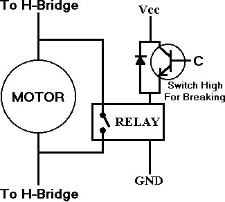
Figure 14: electrical braking system
Another critical issue for coil-based electric actuators like motors, relays and solenoids is the “inductive kickback”, the internal coil of the actuator stores energy as long as it is supplied and operating, but once it is turned off the coil tries to dissipate all this stored energy in a form of a negative voltage spike that can be high enough to damage any sensitive electronic components like controllers, sensors, integrated circuits attached to the actuator control system, to protect the electronics from damage we connect a diode between the low-end of the actuator (the terminal connected to ground) and the power supply similar to the one in figure 12, this diode configuration is called “flyback diode”.
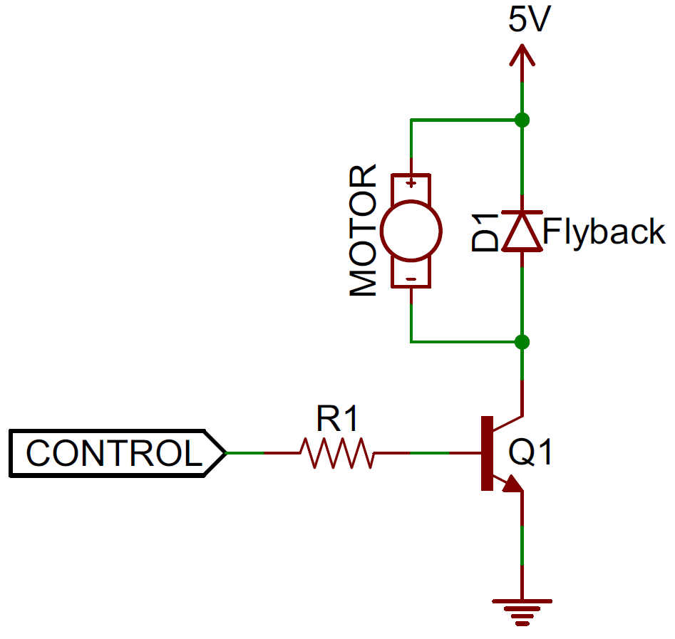
Figure 15: Flyback diode
Position sensing:
There two popular types of sensors used to sense the motor shaft position:
- Hall Effect sensors: they sense the magnetic field from the motor coil or from a magnetic or ferromagnetic material mounted on the motor shaft.
- Optical encoders: basically they are optical sensors; internally they have a source of light, light sensor and a specially designed desk that blocks the light from reaching the sensor when it moves. The desk’s shaft is mounted to the motor’s shaft to sense the motor angular motion and output either an analog or digital code equivalent to the motor position.
Karim El-Rayes,
Vancouver, Canada
December 23, 2015